Ejector Design Calculation
In this article, we will see the Ejector Working Principle
What is Ejector?

Selection of Air Ejectors Part I. Basic design, operating information, and operation limitations of air ejectors. Blatchley Schutte & Koerting An ejector is a pump which uses the jet action of one fluid to entrain and compress another fluid. The high velocity primary stream is produced by expanding a high. This means that if you dont correctly design/select the optimum size/model in your sizing calculation, you will end up with wrong results (basically high or low motive gas flow rate). In your case, you have used very large ejector for your application, that is why you need a high flow rate of motive gas in order to establish the required.
An ejector is a device used to suck the gas or vapour from the desired vessel or system. An ejector is similar to a vacuum pump or compressor. The major difference between the ejector and vacuum pump or compressor is it had no moving parts. Hence it is relatively low-cost and easy to operate and maintenance-free equipment.
Ejector Working Principle
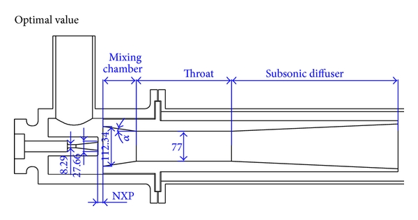
The operating principle of the ejector is the pressure energy in the motive fluid is converted to velocity energy by an adiabatic expansion in the Converging/Diverging
The operating principle of the ejector is the pressure energy in the motive fluid is converted to velocity energy by an adiabatic expansion in the Converging/Diverging Nozzle. Due to the pressure drop of the motive fluid, it will create a low-pressure zone before the mixing chamber. Due to the low-pressure zone, the suction fluid will start to move toward it and mix with motive fluid in the mixing chamber. In mixed fluid enter the diverging portion of the ejector where its velocity energy is converted into pressure energy.
Working of Ejector
The suction line of the ejector is connected to the vessel which is to the kept under low pressure. Refer to the below figure, a high pressure motivating fluid enters at “A” and expands through the converging-diverging nozzle to “B”. The motive fluid will create a vacuum in the mixing chamber refer to to the pressure curve where the pressure is decreased and velocity is increased. Due to this suction fluid “C” (air or gas) from the connected vessel moves toward the mixing chamber “D”. When the suction fluid starts to mix with the motive fluid in the mixing chamber. The velocity of the fluid at the mixing chamber is approximately 600 to 900 meters per second.
Then the mixture travels through the diffuser “E”, its velocity energy is converted into pressure energy. Thereby the mixture gained higher pressure send to the atmosphere or some closed system. Normally the discharge pressure will be 10 to 15 times of the suction pressure
Capacity of Ejectors
The capacity of an ejector is determined by its dimensions. By the required capacity is very high then two or three ejectors are working in parallel. if greater compression is required, two or more ejectors will be arranged in series.
Ejector Installation
Ejectors may be installed at any orientation. However, it is very important to provide a provision to remove the condensate or solid particles from the entrained gases of an ejector. Since any condensed or solid particles may reduce the throughput capacity of the ejectors.
Hence it very important to provide a drain valve installed at low points can be either manual or automatic float operated valves.

Another important thing to check during ejector installation is external loads(Piping load) act on the ejectors. Since any misalignment will adversely affect the performance of ejector.
Ejector Benefits
- Ejectors can be operated with many different motive fluids: steam, air, organic vapour and other gases.
- No moving parts, no lubrication, no vibration. Hence low maintenance cost when compared with other peer equipment.
- Ejectors can be installed indoors or outdoors without restriction.
- Can be installed at any orientation. Hence space requirement will be very low.
- The initial cost is very less and no spares required.
- Easy to handle corrosive and slugging liquids.
Eductor calculations
Ejector Design Calculation Software Download
Eductor calculations
Ejector Design Calculation
I am a new engineer and am looking for pointers on calculating the flowrate needed to move a gas.
We have up to a 150# steam supply as the motive stream. The question is what pressure can we regulate this steam to in order to still maintain the flow.
We are passing the steam at some pressure (this is what is to be determined) through the eductor to induce the flow of a stack gas, which is at or near atmospheric pressure (may actually be a slight vacuum). The outlet of the eductor will have a stack gas/steam mixture that will then be returned to the stack. This flow will serve as a 'fast loop' that every so often an analyzer will pull a 'slip stream' from to test.
Any suggestions as to how to formulate a relation of motive stream to outlet pressure? The eductor used for gases is basically a converging/diverging nozzle from what I understand. The pressure of the motive stream is dropped, to increase its velocity. This in turn sucks the stack gas into the eductor. The two then exit the eductor at an intermediate pressure.
Also, any good sites that thoroughly explain steam usage in refineries? I am looking for something that starts with the basics of steam.
Thank you...