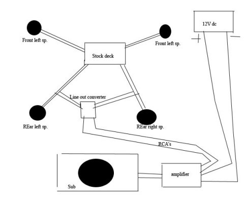
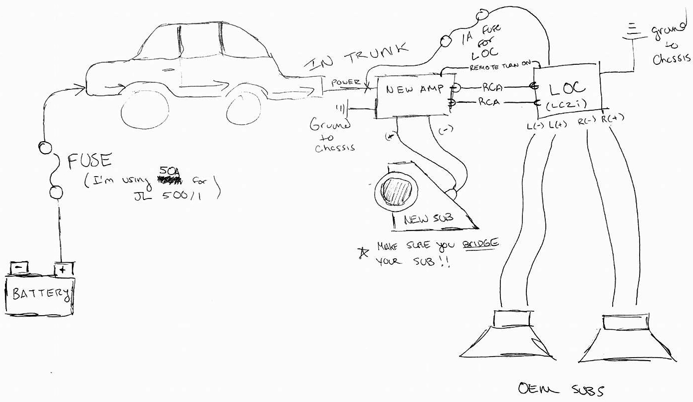
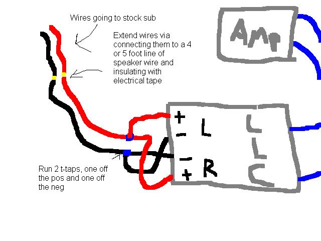
Adjustable Line Output Converter Diagram
- Sni-35 Adjustable Line Output Converter Wiring Diagram
- Metra Cf-ajlo Adjustable Line Output Converter Diagram
- 2 Channel Adjustable Line Output Converter Diagram
- Aw-ajlo Adjustable Line Output Converter Diagram
- Metra Adjustable Line Output Converter Diagram
- Adjustable Line Output Converter Diagram
- Adjustable Line Output Converter Wiring Diagram
- SUBSCRIBE TO MY CHANNEL!is my detailed breakdown on how to install a line output converter into a.
- $15.00 Stinger Select's 2 channel output converter allows for excellent sound reproduction when adding aftermarket amplifiers to an OEM system. Fully adjustable to maximize output signal and matching amplifier inputs to eliminate unwanted noise associated with OEM systems.
Sni-35 Adjustable Line Output Converter Wiring Diagram


Adjustable Line Out Converter; This module will convert you stereo signal from speaker level to a low level signal to RCA for adding a amplifier to stereo setup. Line Output Converter. Brand Information. Item highlights. 4-Channel Premium Adjustable Line Output Converter. 6:1 Step Down With Adjustable Output. 600w Total Maximum Input (150w Per Channel). Super Low Distortion. (25) List price $44.99. The next diagram shows a schematic diagram for a simple line output converter. Line Output Converters – Basic Car Audio Electronics Line output converters (LOCs) are used to convert a head unit s speaker outputs or the. Connect the Gray positive and GrayBlack negative – wires of the source. SVTP erformance The wiring diagram can be found in.
When setting the output gain levels on our line converters (LC2i, LC6i, LC7i, LC8i, LCQ-1 etc…) our goal is to match the gain output, with the gain input sensitivity of your aftermarket amplifier.

Metra Cf-ajlo Adjustable Line Output Converter Diagram
The idea is to send the hottest signal possible out of the converter, without distorting the output of the converter, and also not going over the max input gain of the amp. This helps ensure you get the cleanest signal to your amp as possible.
For example, if the max input gain sensitivity of your amplifier is 5 volts, we will want to make sure the output of the converter does not go over 5 volts.

To do this, we need to properly set the gains on the converter.
Before you begin, do not connect the RCA outputs of the converter to the aftermarket amp yet. Only have the speaker level inputs from the factory system connected to your converter, plus 12 volt and ground. If you are not using signal sense, you will also need a 12 volt trigger wire connected to the converters Remote In terminal in order for it to turn on.
- Set the level on the factory head unit.
You will want to set the level on the factory head unit to about 75% and start playing music. For example, if the head unit goes to 40, bring the volume up to about 35.
2.Bring the gains up on the converter
Slowly bring up each channel gain until the maximized light begins to flicker, and then back off until it stops.
The maximized light lets you know you are getting to distorting the output of the converter.
2 Channel Adjustable Line Output Converter Diagram
***THE MAXIMIZED LIGHT ENSURES YOU DO NOT DISTORT THE OUTPUT OF THE CONVERTER, IT DOES NOT ENSURE THAT YOU WILL NOT DISTORT THE INPUT OF YOUR AMPLIFIER*** The maximized light is a handy tool if you do not have a volt meter handy. It serves as a guide in helping you not distort the input of the amplifier (see below for more info).
After you bring up the gains on each channel, it’s time to connect the converter outputs to the aftermarket amplifier.
3.Connect RCAs from the converter to your amp
It is crucial to make sure the input gain/sensitivity knobs on the amp are turned all the way down.This will ensure the amp will be able to accept the highest level signal that it is rated for. We do this because most amplifiers can accept between 4 and 6 volts. Our converters have 12 db of gain and have the potential to output up to 8.5 volts.
Aw-ajlo Adjustable Line Output Converter Diagram
4. Send signal thru the system
Metra Adjustable Line Output Converter Diagram

Adjustable Line Output Converter Diagram
Once you have made all of your connections from the converter to your aftermarket amps, it’s time to turn on the head unit and send some audio thru the system.
Adjustable Line Output Converter Wiring Diagram
If you bring the volume all the way up and you think it’s not loud enough, you could then go to the input gains on the amp and bring them up a bit. Typically, you shouldn’t have to bring the input gains up more than 25% or so.